Signal Gauge Set-Up
|
Instructions
- Prepare a judgement master ( standard sample ) and hold a signal gauge on a stand, etc.
- Adjust and fix the position of judgement master so that a gauge pointer indicates zero, and move the contact point (8) up and down several times so as to confirm the pointer’s stable position.
- When setting a lower limit of tolerance value, remove the master and turn the lower limit setting knob (5) so as to adjust a pointer at a certain graduation.
- When setting an upper limit of tolerance value, turn the upper limit setting knob (6) so as to adjust a pointer at a certain graduation while fully pushing up the contact point (8).
- After setting the upper and lower limit, move the spindle (9) up and down several times to confirm that a pointer’s indication is within the tolerance value.
* Stem or back cover with lug is used to support the gauge.
|
 |
Instructions
- Prepare a judgement master ( standard sample ) and hold a signal gauge on a stand, etc.
- Prepare a dial gauge for setting tolerance value No.107 ( 0.01mm to 10mm ) and remove the dust protective cap (4) by a hexagon wrench attached to the gauge.
- Turning the lift knob (3) allows the spindle (5) to move up and down. The pointer of dial gauge moves according to its movement.
- Connect this checker with a signal box or a controller.
- Prepare a judgement master ( standard sample ), on which push this checker to the position where the lower limit of tolerance value can be set, and fix it by a supporting device.
- Set the indicator of dial gauge at zero of a dial and turn the lower limit setting knob (1) fully in the clockwise direction.
- Set the upper limit of tolerance value at a certain position while turning the lift knob (3) in the clockwise direction.
- Turn the upper limit setting knob (2) in order to adjust the indications ( signals ) of signal box or controller to the switching position of OK and +NG at the upper limit of tolerance value.
- Remove the master and turn the lift knob (3) in the counter clockwise direction to set the lower limit of tolerance value.
- Turn the lower limit setting knob (1) to adjust the indications ( signals ) of signal box or controller to the switching position of OK and -NG at the lower limit of tolerance value.
- Move the spindle (5) up and down several times by the lift knob (3) to check the right adjustment.
- After your setting, turn the lift knob (3) in the counter clockwise direction until the spindle (5) is fully pushed down.
- When you use this checker without dial gauge, never forget to mount the dust protective cap (4) on it.
* Stem is used to support this checker.
|
Signal Gauge Connections Diagram
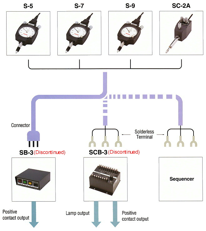
*Gauge are connected to a signal box by attached connectors.
When connecting with a signal controller or a sequencer, remove the connectors and use solderless terminals.